News Releases
Mitsubishi Electric to Launch 4-terminal N-series 1200V SiC-MOSFETs Helps to reduce power consumption and physical size of power-supply systems
FOR IMMEDIATE RELEASE No. 3382
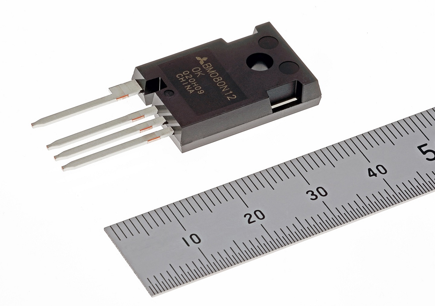
TOKYO, November 5, 2020 - Mitsubishi Electric Corporation (TOKYO: 6503) announced today the coming launch of a new series of silicon-carbide metal-oxide-semiconductor field-effect transistors (MOSFETs), the N-series of 1200V SiC-MOSFETs in a TO-247-4 package,1 which achieves 30% less switching loss compared to the existing TO-247-3 package2 products. The new series will help to reduce the power consumption and physical size of power-supply systems requiring high-voltage conversion, such as electric vehicle (EV) on-board chargers and photovoltaic power systems. Sample shipments will start this November.
- 1Separates the driver-source-terminal from the power-source-terminal, unlike conventional 3-pin packages
- 2Mitsubishi Electric press release on June 16, 2020: https://www.MitsubishiElectric.com/news/2020/0616.html

N-series 1200V SiC-MOSFET in TO-247-4 package
Product Features
- 1)Four-pin package helps reduce power consumption and physical size of power-supply systems
- SiC-MOSFET chip with good figure of merit (FOM3) of 1,450mΩ-nC and high self-turn-on tolerance is mounted on TO-247-4 package, which is equipped with independent driver source terminal as well as conventional 3-pin package.
- Adopts four-pin package to reduce parasitic inductance, a problem in high-speed switching. Eliminating gate-source voltage drops due to current variations helps to reduce switching loss by approximately 30% compared with TO-247-3 products.
- Using a higher carrier frequency4 to drive the new power semiconductors helps to reduce switching-power loss, enabling smaller and simpler cooling systems as well as smaller reactors and other peripheral components, thereby helping to reduce the power consumption and physical size of overall power-supply systems.
- 3Performance index of power MOSFETs, calculated by multiplying on-resistance by gate-drain charge (100°C junction temperature). Smaller values indicate better performance.
- 4Frequency that determines the ON/OFF timing of switching element in inverter circuit
- 2)Six models for diverse applications, including AEC-Q101 compliant models
- New lineup includes models compatible with Automotive Electronics Council's AEC-Q101 standards for use not only in industrial applications, e.g. photovoltaic systems, but also EV applications.
- Creepage distance (shortest distance over surface between two conductive parts) between drain terminal and source terminal made wider than in TO-247-3 package products for more flexible application, including in outdoor installations where dust and dirt easily accumulate.
Note
Note that the press releases are accurate at the time of publication but may be subject to change without notice.


